Introduction to Computer Networking
TCP/IP and the Five Layer Network Model
Below is a basic table outlining the five layers:
| Layer Name | Protocol | Protocol Data Unit | Addressing |
|---|---|---|---|
| Application | HTTP, SMTP, etc. | Messages | n/a |
| Transport | TCP/UDP | Segment | Port #’s |
| Network | IP | Packet/Datagram | IP Addresses |
| Data Link | Ethernet, Wi-Fi | Frames | MAC Address |
| Physical | n/a | Bits | n/a |
- Physical Layer: The actual computing device(s) and the cables that connect them, sends and receives signals
- Data Link Layer: Also known as the network access layer, it’s our first protocol to interpret signals sent from and to each computing device
- Ethernet is our first and most common protocol, which is responsible for transporting data across the network
- Network Layer: Also know as the internet layer, this layer is what actually allows the computing devices to communicate with each other. Helps the data move along from your computer to a server for a webpage or application. Routers are used to accomplish this.
- Routers with communication actually define a internetwork, and the largest and most popular of these is obviously, the internet.
- IP is the protocol the computing devices follow to ensure accurate travels through routers.
- Transport Layer: This is where the decision to dictate which device is the client (using an app) versus the server (where the information is stored).
Cables
Quick note on cables since I think Khan Academy went into enough detail on this. One new thing I picked up was this term, Crosstalk. So, Cat5 cables were the most common copper cabling for some amount of time. Most are being replaced by Cat5e and Cat6 due to this issue of Crosstalk, where one wire in the cable unintentionally picks up the electrical pulse from a different wire.
Hubs and Switches
A Hub is a physical computing device that allows for multiple connections to multiple computers simultaneously. All devices on the hub can communicate with each other, and it’s the hub’s job to facilitate that communication. It’s not very good at this though, and will send the data to all devices on the network, and is accepted by only the intended device.
Unfortunately, Collision domain is common on hubs, or a forced piece of the network where only a single computer can communicate. Since multiple devices sending data signals all at once, they can interrupt or interfere with one another.
To avoid this, a better alternative for hubs are Switches, or switching hub. Hubs are actually on Layer 1, a physical computing device. Switches however, are a layer 2 device. This means it can actually inspect the contents of Ethernet, and can accurately determine where the data is supposed to go.
Routers
While Hubs and Switches work in LAN, or Local Area Network, Routers are a powerful tool that allow for communication and transfer of data across independent networks.
Routers would be a layer 3 device, and can inspect IP data to make the call on where to send information. The routers have tables in them that contain information on past IP addresses to keep for easier routing. Once the router determines where to send the information, the data is sent to the ISP (Internet Service Provider) that has far more complicated routers than you’ll find at home.
Routers share information with one another using a protocol called Border Gateway Protocol, or BGP. BGP allows for faster and more optimal routing of data.
Physical Layer
Modulation is the process of transferring electrical charges through copper cables. We can get more specific and talk about in relation to computers, it’s called line coding, which encodes and decodes the states of electricity as 1’s and 0’s.
One cable in almost every room in the country is a basic twisted pair cable. These cables have pairs of copper wires twisted around each other, allowing for more accurate transfer amongst pairs. This also allows for the process of sending and receiving information at the same time, known as duplex communication. Full Duplex is where two devices are simultaneously communicating with one another, while Half Duplex is when it has to send and receive in turn.
Ethernet Cables are the most common cables you’ll see, and they can also go by CAT. Ethernet cables connect to routers, which we know provide us with internet access.
Prior to Ethernet cables, you used to just lay out two copper wires adjacent to one another and call it a day. Communication this way was clearly inefficient due mainly to electromagnetic interference (EMI), radio frequency interference, (RFI), and crosstalk. The previous three problems are what lead to the modern standard of a CAT 5 or CAT 6 cable.
UTP, or unshielded twisted pair, are common where the previous three issues aren’t a big deal. If they are, you would use either a shielded twisted pair (STP) that uses braided aluminum and/or copper shield around all four twisted pairs, or a foiled shielded pair (FTP) that uses thin foil shielding to wrap around the pairs.
Straight-through cables are the types of cables you see everyday, as they connect computers to routers. The colors on straight-through cables are different depending on the communication, and are consistent from end to end (two dedicated to sending, two to receiving).
The form factor or name we use for the ports of these cables are RJ 45. RJ 45 ports fit RJ 45 plugs, and the ports often have LED’s indicating what’s going on. Usually, the top left is yellow and indicates a connection and the top right is green indicating transfer of data.
This is a really awesome video on how to actually strip, cut, and crimp a wire for RJ 45.
Data Link Layer
Since we’re using Ethernet cables for communication, I think it makes sense to call the protocol in which you send and receive data over them Ethernet. The Data Link Layer really helps the following layers out, by standardizing the information being received regardless of the type of machine it’s coming from, abstracting out the complexity of the physical layer.
What makes Ethernet so special is it’s ability to take in information from a wired or wireless connection and make it accessible regardless. It also evolved the way computer networks function, by reducing the amount of crosstalk and other previous issues by introducing a standard called carrier sense multiple access with collision detection, or much simply CSMA/CD. Basically, it can determine when a channel or line of communication is open and free of use, to avoid collision or unintelligible data.
Due to how data is transferred, unique identifiers were necessary to keep data from flowing to the wrong destinations. This led to MAC Addresses, or Media Access Control address. A 48-bit number group of six groupings of two hexadecimal pairs. The first three octets are an organizational unique identifier, or OUI. This is good to know so you can tell what type of hardware the signal is coming from.
When dealing with multiple devices on a network, there are three main ways of communicating with them; Unicast will send data to all devices but only be accepted by the intended destination, Multicast will send data to all devices and acceptance is dependent on hardware decisions made prior, and Broadcast will be sent and accepted by all.
Packets at this point have been used an ambiguous term; it really is just meant to represent some data going from point A to point B. At the data link layer, or more specifically when talking about Ethernet, we call these packets Ethernet Frames. Frames are intentionally crafted pieces of data made up of the following parts:
- Preamble: 8 bytes long and can be split into two, mostly used for buffering between frames or synchronizing device clocks, and the final byte is known as the Start frame delimiter (or SFD) that signals to the destination device that the preamble is done and it’s about to start getting data.
- Destination MAC Address: 6 bytes
- Source MAC Address: 6 bytes
- Ether-type Field: 16 bits long and describes the protocol being used by the contents of the data to the frame
- OR VLAN Header: tells the frame its a VLAN frame, and the Ether-type follows. Virtual LAN lets you have multiple LAN’s on the same physical equipment. These are often used to segregate traffic, like in a business they might use a VLAN for all phone traffic, and keep computer traffic separate
- Payload: The actual data being transferred, contains the remaining three layers of information
- FCS: Frame check sequence: or the 4 byte number that represents a checksum value for the entire frame used in a CRC, or cyclical redundancy check, to ensure data integrity
Network Layer
Switches connecting devices with MAC Addresses is a pretty easy job for the switches; it quickly learns the information on the connected devices and can be quite fast. MAC doesn’t scale that well since there are so many devices, and there’s no way to structure their addresses. The Network layer and their protocols seeks to fix this.
IP Addresses are 32-bit long numbers made up of four octets, and a single octet (8 bits) is usually some number between 0 and 255.
IP addresses belong to networks, not the devices attached to the networks, and are often given to organizations with certain patterns to differentiate them/help the flow of traffic.
Modern networks allow you to connect any device and it will be given an IP address through a process called Dynamic Host Configuration Protocol.
The video provided went into detail on exactly what makes up the IP datagram, and it’s incredibly similar to how it was described through Khan Academy. Two things I learned that were new to me were the Time to Live (TTL) field that tells the packet how many times it should be forwarded before it dies to prevent loops, and fragmentation as the name for the concept of splitting the datagram into parts if it cannot fit in one single datagram.
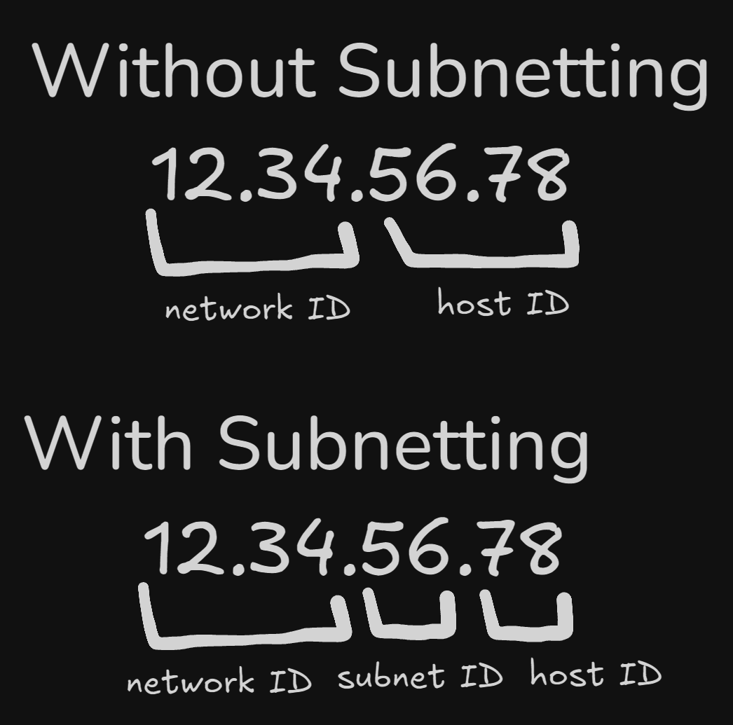
The first octet is the network ID, and the rest of the three octets make up the host ID. The Address class system determines how each address is structured, and there are three main types of classes; A, B, and C.
| Class | Left-Most Bit | Starting IP | Last IP |
|---|---|---|---|
| A | 0xxx | 0.0.0.0 | 127.255.255.255 |
| B | 10xx | 128.0.0.0 | 191.255.255.255 |
| C | 110x | 192.0.0.0 | 223.255.255.255 |
Class A is like above; where class B has the first two octets being the network ID, and class C has the first three octets make up the network ID. This system is still in use, but has sometimes been replaced by CIDR, or Classless Inter-Domain Routing.
ARP, or Address resolution protocol, is how we can use MAC address and IP addresses together. An ARP table, or a list of IP address and MAC addresses associated with them, is kept on almost every network connected device. If the device doesn’t have the requested address saved, it can broadcast to other devices on the network until someone knows it, and sends it to the original sender to be delivered.
Subnetting is another important concept at the network layer. Subnetting is the process of breaking down one large network into smaller, related sub-networks. Apparently, incorrect subnetting setups are common and can be resolved by an IT specialist.
As we saw previously, the different types of classes are recorded via the Address class system. When we want to send a message, the class is determined, followed by the gateway router responsible for that class. The gateway router has subnets of different distributions, depending on various factors. The gateway router is just an entry point to these core or local routers which are then distributed on their way to the client.
Up until this point, we’ve understood an IP address made up of two parts; the network ID and the host ID. In subnetting, a part of the host ID can actually become part of what we call the subnet ID.
The internet level, or core router only uses the network ID to send information, while the gateway router will use the additional information to more accurately send information.
Subnet ID’s are determined by Subnet masks, which are 32-bit numbers that are written as four octets in decimal. Very similar to an IP address, but it determines which part of the address will be the subnet ID.
The subnet mask has two parts; the mask, which is a bunch of 1’s, and the rest are zero’s meant to represent what we keep as the host ID. It’s pretty confusing, but this does a great job of going over it.
Eventually, as time caught up and the need for more accessible network space skyrockets, CIDR, or classless inter-domain routing became a standard. Using a new slash notation along with subnetting, it allowed for the subnet ID and network ID to combine, allowing for more flexibility and more available networks per company.
Routing is an extremely complicated topic, while also being a rather straightforward concept. Essentially, a router is just a device that forwards network traffic depending on the destination of said traffic. The steps the router does are as follows:
- Receive data packet/information
- Examine destination IP of data packet
- Look up IP address for destination network in the router’s routing table
- Forwards traffic to destination closest to destination determined by the routing table
The routing table previously mentioned is also a rather simple construct, mostly made just to make the life of your router easier. It’s made up of four columns or parts;
- Destination Network: Each network the router knows about, the network ID and net mask
- Next Hop: The IP address of the next router that should receive the datagram on it’s way to it’s destination
- Total Hops: How many hops it’ll take to reach the destination via that route (need confirmation on this)
- Interface: The address of the interface in which to forward information too
Routing tables should always be updated with the most up to date information, to avoid closures, collisions, or other unexpected activity. One of the ways that’s accomplished is through routing protocols. This shouldn’t come as a surprise- everything has protocols. These protocols help share information.
There are two main protocols; Interior Gateway Protocols or Exterior Gateway Protocols. Interiors can be split even further into Link State Routing Protocols or Distance-Vector Protocols.
Interior protocols share information within a single autonomous system, or a collection of networks that are all controlled by a single network operator. Think of connecting two LANs for a company; two distinct buildings that need to transfer information to one another.
Distance-Vector protocols are how routing tables started; a router takes a list of it’s available networks with how many hops for each, then shared with each device in it’s network. This is pretty inefficient, as the information is limiting and usually only about immediate neighbors.
Transport Layer
We rely on the transport layer for a myriad of reasons, mostly to help do exactly as the layer is called, transport the actual data from client to server and vice versa.
One concept vital to the transport layer is Multiplexing, or allowing a node existing on a network to actually help direct data flow, or traffic, to where it needs to go. It then uses Demultiplexing to receive and accurately place the received data to where it should be displayed or kept.
Multi- and Demultiplexing use ports, or places where expected data is received. These ports are 16-bit numbers that acts like the delivery room for different services/protocols. For example, something like HTTP is port 80; this means that when requesting information from an unencrypted web page, traffic gets sent to port 80 on that device. Another common port is 21, usually reserved for FTP, or file transfer protocol. FTP is pretty old but is still in use today.
There’s a video segment on exactly what makes up the TCP packet, but I went over that decently well in AP Computer Science Principles - Unit 2, so you can check there for more details. It also touched on the three-way handshake, which is also gone over in the same note.
A new concept to me is the term socket, which is the instantiation of a TCP connection. It’s a little vague, so a good example would use ports; you can send data to any open port, but only the port with the accepting socket from some program will actually respond to it.
Sockets have a few different states, which are outlined below:
- LISTEN: TCP socket is open and ready for any incoming connection, importantly this would only show up on the server side, not the client
- SYN_SENT: A request for synchronization, sent from exclusively the client side. This does not mean a connection has been established yet
- SYN_RECEIVED: The socket that was just in a LISTEN state has received the request to synchronize, or the SYN_SENT (sends out the SYN/ACK flags)
- ESTABLISHED: TCP connection has been made successfully on both sides, seen on both client and server side
- FIN_WAIT: A FIN signal has been sent but no ACK has been received
- CLOSE_WAIT: Connection has been closed, but only on the TCP layer; the application actually has to release the socket to be fully complete
- CLOSED: Connection fully cut and communication is no longer possible
They also explain TCP ports and sockets in a different way than I’ve seen before. They define the segment of a TCP datagram as the code that details which port should be used to make a connection, and it achieves this on the server side of the connection by telling the server which port to watch for incoming data requests. Once told, that port is now a socket.
A firewall is actually a device/software that will stop incoming traffic if it doesn’t pass as expected traffic. They can be seen at any layer, but are mostly seen at the transport layer. They can help redirect the flow of traffic to specific ports, or even cut off access to ports entirely.